The problems associated with the original Gottlieb driver board are four-fold - connections to the CPU can be corroded and cause poor driver/lamp signals; the MPS-U45 is a very difficult transistor to find; the old 2N3055 transistors burned holes through the PCB, and a failed driver board will cause as much damage to a sound board as a failed sound board would do in reverse. Ni-Wumpf has redesigned the System 80 driver board to address all these issues, and adds in a few more features that should prove useful.
- Each solenoid has fault detection circuitry that identifies failed playfield/driver board components
- FET solenoid transistors
- Higher rated transistor components for all circuits
- Surface Mount components for PCB density. Transistor arrays to reduce cost
- Modern component architecture uses currently available parts. SMT rework is a bit harder to service but less expensive in component costs.
- Open-collector interface to the sound board to buffer against failures generated to/from that source
- Diode isolated grounds to prevent playfield lamp problems from the board
Each driver circuit is equipped with fault detection circuitry and LED's that will blink when actuatued, and light steady to indicate circuit failure.
Note that the LED will remain lit when a game does not support the associated playfield driver components. Similarly, it will light if the fuse is blown, or the coil is shorted.
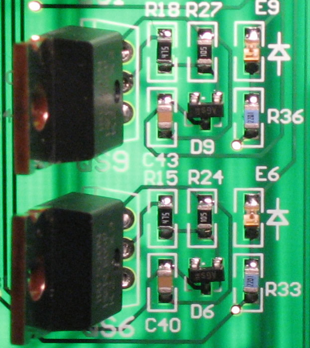
The board was designed to follow the original Gottlieb component functionality as described on the original driver board. So where the original board had ICs Z1 - Z12, this board has the same numbered components. Where the lamp transistors were Q1 - Q52, this board has similarly labeled components that are numbered Q0 - Q51. Why - you ask? I was *always* confused by L0 corresponding to Q1 on the original schematics, and I wanted THIS board to line up the component numbering with the lamp assignments on the playfield schematics! And finally, where the original board had solenoid 1 - 9 output transistors, this board has FETs QS1 - QS9. In this way, the user can follow the original schematics when troubleshooting the board.
Please note: the schematic manual is coming...